
|

|
PLEASE NOTE: While the photos here are representative for this procedure, they may not be of the specific equipment you are repairing.
Important Disclaimer: This information is intended to assist you in repairing your keyboard, which is presumably no longer
under warranty. Doing this type of work will almost certainly void any existing warranty coverage. Syntaur offers this information as a free service,
and makes no warranties of any kind regarding its use. You are solely responsible for any damages, problems, or injuries resulting from opening up
and working on your equipment. Unless otherwise indicated, the keyboard should be powered off and unplugged while these procedures are being done; otherwise,
you can be exposed to potentially fatal voltages. If you do not feel comfortable or competent in performing these tasks, we strongly recommend taking your keyboard to a
service center. |
You may also want to view:
Opening Up a Roland Juno-106 or HS-60 Keyboard
Calibrating a Roland Juno-106 or HS-60 Synthesizer
|
This procedure will walk you through the process of calibrating (tuning) a Roland Juno-106 (or HS-60) synthesizer. It requires a voltmeter, a frequency counter or tuner, and an oscilloscope. It also requires working on the keyboard with the power on and the power supply exposed, so this calibration should not be attempted unless you are confident in your abilities to work safely, and to use the necessary equipment.
Note that any time you replace a voice chip on your synthesizer, you will need to recalibrate at least that voice. Make sure the keyboard has been powered on for at least 10 minutes to warm up prior to any calibrations, and perform the calibration steps in the order they are listed here. Power on the Juno-106 while holding down the KEY TRANSPOSE button; this will put the keyboard in Test Mode. The display will read '-_'. Press the Poly 1 and Poly 2 buttons together, and now for each note played, the display will show which voice is sounding ('-1' through '-6').
(Click photo to enlarge it.) |
 |
|
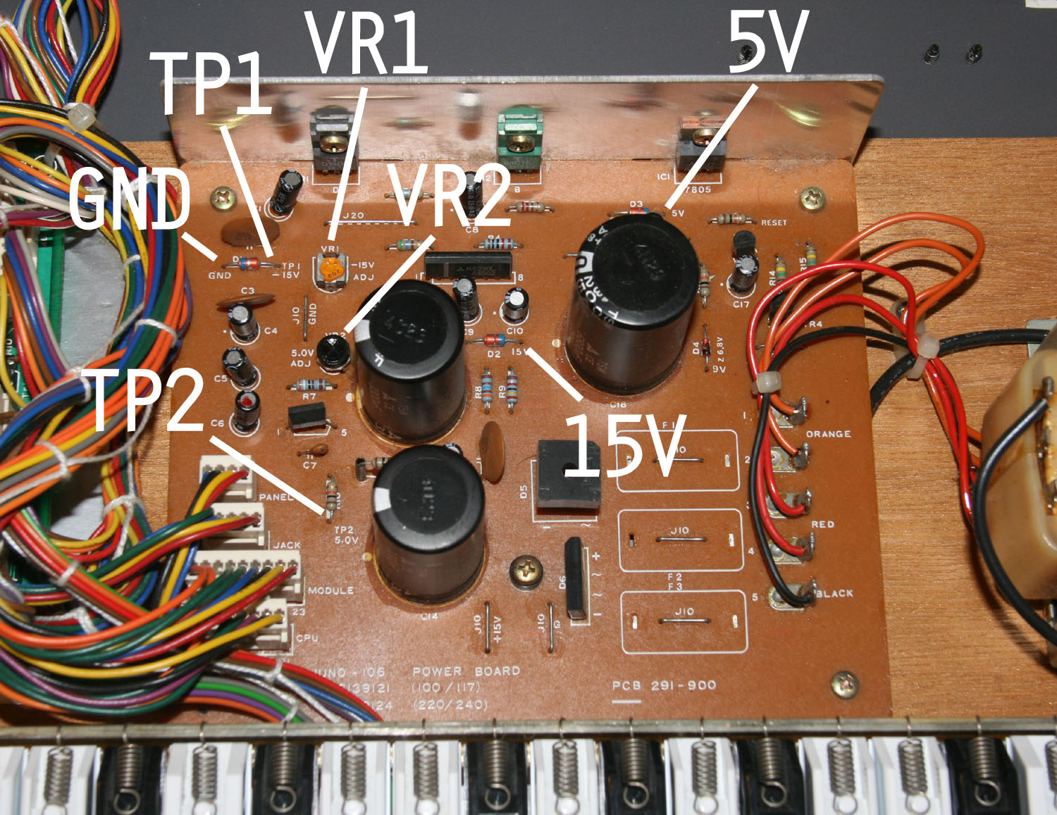
POWER SUPPLY Use a voltmeter, grounded to GND (the diode at left rear corner of PS board). Measure TP1 (opposite leg of diode). Adjust VR1 for -15VDC. Measure TP2. Adjust VR2 for +5VDC. Verify +15VDC at '15'. You cannot adjust this. Verify +5VDC at '5V'. You cannot adjust this.
(Click photo to enlarge it.) |
 |
|
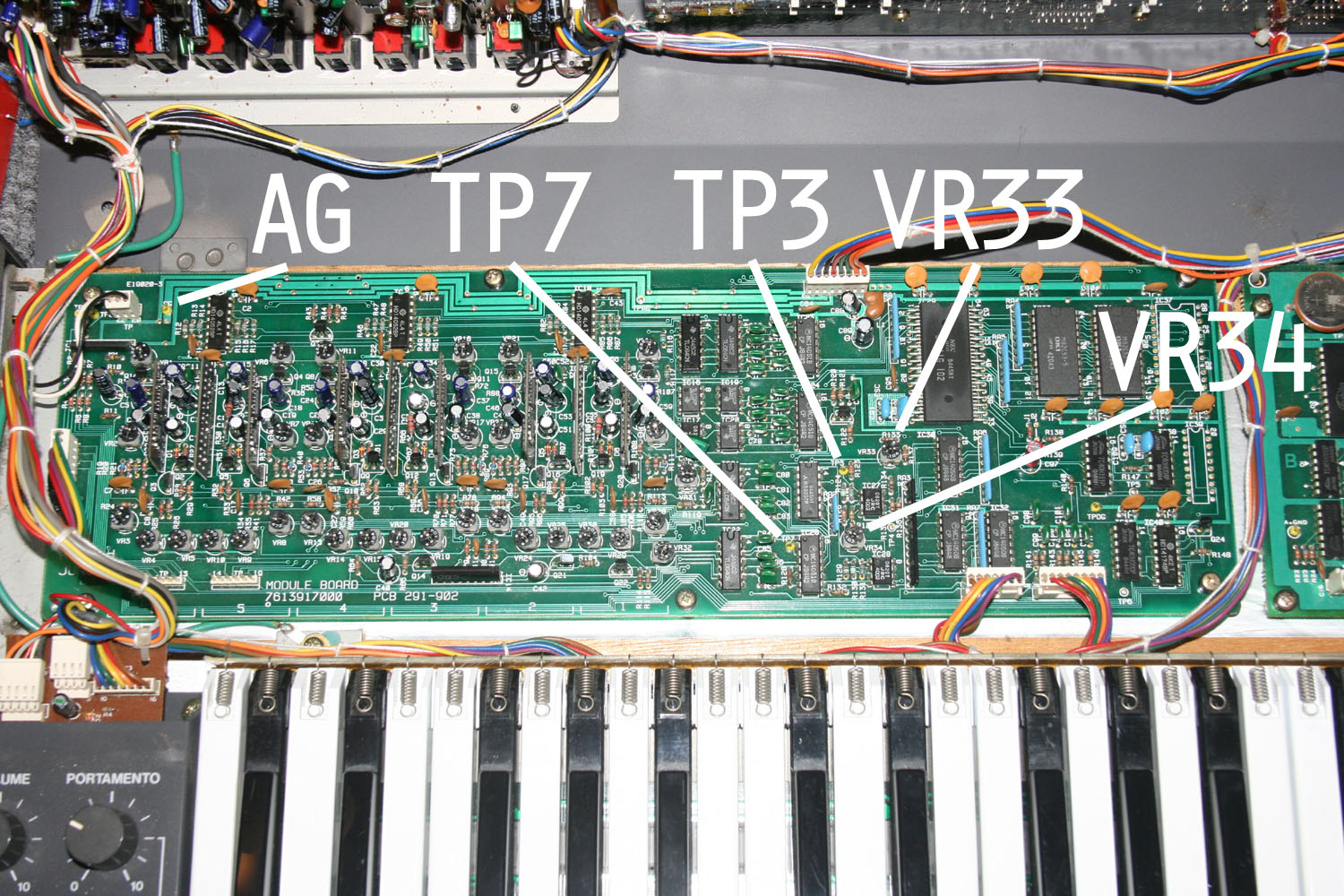
MODULE BOARD 1. DCO CV OFFEST With the voltmeter, measure the DC voltage at TP3 on the Module Board. Press the MIDI CH button, and this voltage should go to 0. Adjust VR33 to get 0 volts. (Do not press any keys.) 2. VCA BIAS Measure the voltage at TP7. It should be between +0.25 and +0.27V. Adjust VR34 if necessary.
(Click photo to enlarge it.) |
 |
|
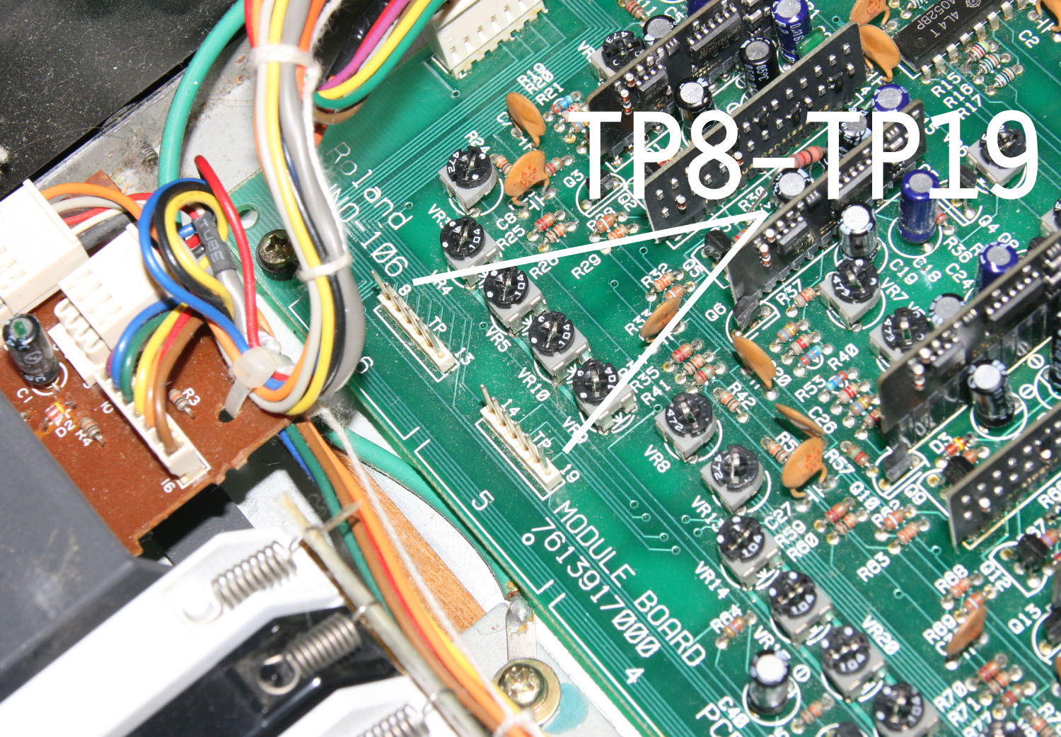
3. VCA OFFSET Ground the oscilloscope lead to the analog ground (AG) at the left rear of the module board. Clip onto TP8 (TP8 though TP19 look like two unused connectors on the left front of the board). Press the Bank 1 button on the panel. (This loads the correct program for this test.) Play a note, and make adjustments for the minimum (smallest amplitude) reading on the oscilloscope. Voice 1 uses TP8, adjust with VR30 Voice 2 uses TP9, adjust with VR25 Voice 3 uses TP10, adjust with VR20 Voice 4 uses TP11, adjust with VR15 Voice 5 uses TP12, adjust with VR10 Voice 6 uses TP13, adjust with VR5
(Click photo to enlarge it.) |
 |
|
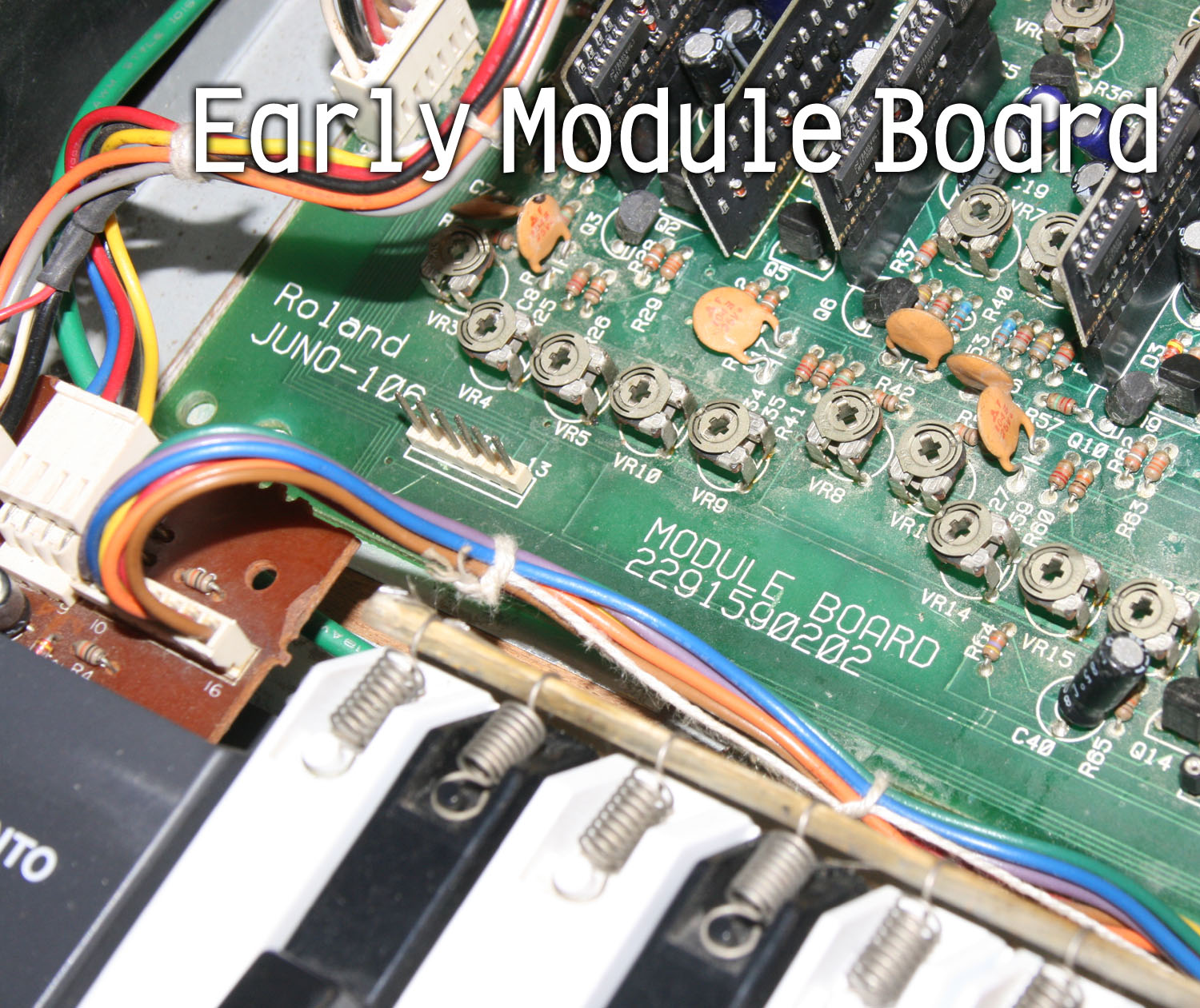
4. VCF RESONANCE Press the Bank 3 button on the panel. Play middle C (you don't need to hold it down), then use the oscilloscope to observe the amplitude of each voice. They should all be identical, and should read 4.8V peak-to-peak. The early module boards (shown above) did not have the row of test points 14-19. Instead, you will need to connect to the center pin of trim pots, as indicated below. Voice 1 uses TP19 (or center pin of trim pot VR27), adjust with VR26 Voice 2 uses TP18 (or center pin of trim pot VR22), adjust with VR21 Voice 3 uses TP17 (or center pin of trim pot VR17), adjust with VR16 Voice 4 uses TP16 (or center pin of trim pot VR12), adjust with VR11 Voice 5 uses TP15 (or center pin of trim pot VR7), adjust with VR6 Voice 6 uses TP14 (or center pin of trim pot VR2), adjust with VR1 |
|
5. VCF GAIN Press the Poly 1 button. Hold down (or tape down) middle C, and use the oscilloscope to observe the amplitude of each voice. They should all be identical, and should read 6.0V peak-to-peak. Voice 1 uses TP8, adjust with VR27 Voice 2 uses TP9, adjust with VR22 Voice 3 uses TP10, adjust with VR17 Voice 4 uses TP11, adjust with VR12 Voice 5 uses TP12, adjust with VR7 Voice 6 uses TP13, adjust with VR2
|
|
6. VCF FREQUENCY Play middle C, and measure the frequency of each voice at the test points below; adjust to make each read 248Hz. You can use a frequency counter for this (some multimeters have frequency counters), or you can play through speakers and use an iPhone app such as Fine Tuner. Voice 1 uses TP8, adjust with VR29 Voice 2 uses TP9, adjust with VR24 Voice 3 uses TP10, adjust with VR19 Voice 4 uses TP11, adjust with VR14 Voice 5 uses TP12, adjust with VR9 Voice 6 uses TP13, adjust with VR4
|
|
7. VCF WIDTH Now play the C two octaves up from middle C, measure the frequency of each voice, and adjust each to read 992Hz. Voice 1 uses TP8, adjust with VR28 Voice 2 uses TP9, adjust with VR23 Voice 3 uses TP10, adjust with VR18 Voice 4 uses TP11, adjust with VR13 Voice 5 uses TP12, adjust with VR8 Voice 6 uses TP13, adjust with VR3
|
|
8. VCA GAIN Press the Bank 6 button. Playing any key should produce white noise. Use the oscilloscope to see the noise at TP8, and use VR32 to adjust the amplitude to 4V p-p.
|
|
9. PWM Press the Bank 5 button. Play middle C, and use the oscilloscope to observe a square wave from each voice. Confirm that each voice shows a 50% duty cycle (the upper and lower peaks of the wave should be identical in length). Voice 1 uses TP8 Voice 2 uses TP9 Voice 3 uses TP10 Voice 4 uses TP11 Voice 5 uses TP12 Voice 6 uses TP13 Now, slide the PWM knob on the panel to 10, and confirm that each voice shows a duty cycle of about 95% (one peak very long, the opposite peak just a narrow spike).
|
|
The six voices are now all calibrated. Press the Manual button, and as you cycle through the voices, they should sound identical in pitch, loudness, and timbre. The filter is now calibrated as well, and you can test this by turning the pulse and sawtooth off, and setting the suboscillator and noise all the way down. Now, make the filter self-oscillate by setting the resonance fully on - you should now hear a sine wave sound, and the FREQ slider will control its pitch. Set the VFC ENV and LFO sliders all the way down, and with the VCF KYBD slider fully upward (this opens the filter to match the keyboard tracking), the filter should play chromatically as you play the keys.
|